
Ionisation of water pipes demonstrated
It's one thing to demonstrate by epidemiology that ionisation is caused by mains power being connected to water pipes, but it's quite another to be able to actually see the ionisation occurring. So this page aims to demonstrate the effect by corollary. The following electrical circuit can be built at home using parts readily available at your local electronics store. For New Zealand and Australian residents, Jaycar catalogue numbers are included and a website link for mail order.
To recap, the following diagram shows how there are multiple return paths for power in the AC system. The one which we are focusing on here is the path which uses the impedance of the ground or earth to complete the circuit.
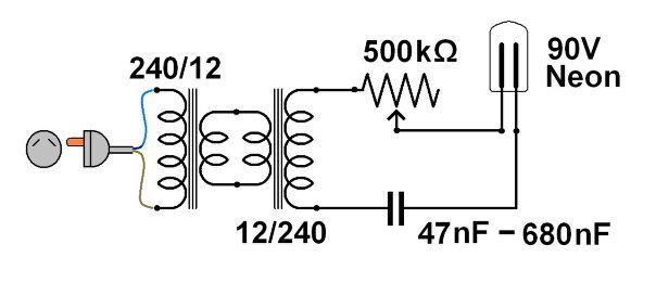
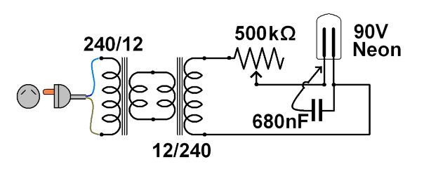
First we need to look at the path which uses capacitance in its return. This may seem obvious, but its a useful exercise as an introduction (and its fun to do). The circuit uses a capacitor to complete the circuit. We can use two values of capacitor, the smaller of which will not let the circuit work and the larger which will. See how you go!
Remember that this circuit involves mains voltages, so the golden rule is to never touch any wires when the circuit is plugged in. Point to point wiring is used in the demonstration circuit, with the potentiometer mounted on the tag strip. ALWAYS keep one hand in your pocket when working on live mains equipment: then you can only touch one phase. If you think you might keep this circuit or its developments as a demonstration, then put heat shrink tubing over the live wires.
With this circuit each of the capacitors can be soldered in in turn to see the effect. Although the neon needs only 90 volts to start, the full range of voltage can be used to see the effect on the neon without destroying it.
So this little circuit shows us that capacitance can be used to complete an AC circuit if the capacitance is great enough (though still very small in real terms).
The neon bulb uses two electrodes in a neon gas and there are two points to note:
-both electrodes are ionising the neon gas, and
-the electrodes are not touching each other.
The capacitance in the bulb is negligible, so while capacitance can be used to complete a circuit the circuit within the bulb itself must be completed by something other than capacitance, and this is impedance. Like capacitance, impedance has no physical connection or contact between the two conductive electrodes in the bulb, the circuit being completed by ionisation of the neon gas around the electrodes.
The arrangement of water pipes with one on either side of the street is quite common. The larger pipe is called a fire main, with capacity to suit, and the other is called a rider main. Both mains supply drinking water and both are parallel to earthing wires.
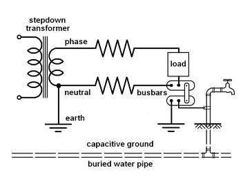
Here the power transformer has the low voltage side grounded to earth. The neutral wire in any building is also grounded to earth by the link between the bus bars: but there are at least two paths via earth - one through the earthing rod and one through any metal water pipes. The return path through the water pipe has then to complete the circuit through the ground.
First test
The parts list for this circuit is in this link. We're using two little transformers back to back to get isolation. The lead and plug can be cut off any dead gizmo and the whole lot mounted on a block of wood.
Second test
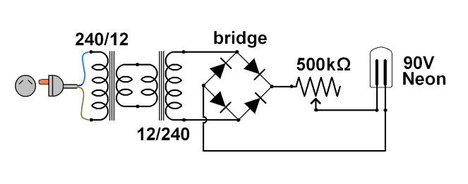
For this test we've added a full wave bridge to rectify the AC to "dirty" DC:
Now, when we plug the circuit in we get a different effect in the neon bulb:
If we refer back to the first diagram we can see that with AC power there will be ionisation occurring both at the transformer earth and at the water pipe earth. In a typical urban street the transformer earth will be parallel to the street and there will be water pipes also parallel to the street: in other words the electrodes are parallel in our neon bulb and represent the parallel placement of earth wire and water pipes as electrodes.
� Stephen G Butcher & Dr Jim Sprott (Posted 17/11/08)
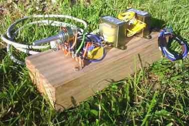
The transformers and tag strip are screwed to the block of wood, and the capacitors and bridge (see second test below) are hot glued into place. The pot is soldered to the tag strip, as is the neon, and the rest is point to point.
Last test
For this test we revert to the neon driven by AC only, so we reconnect the output transformer leads to the pot and neon. Then we can take flying leads from the 680 nF capacitor and solder one lead to one leg of the neon. The other flying lead must be insulated, not bare, so we can momentarily touch this against the remaining leg of the neon. So our circuit will look like this:
It would seem that the capacitor is the path of least resistance. This would mean that the return paths are roughly in order of preference:
- the resistive path through the neutral wire,
- the resistive path through earth,
- the resistive path through water pipes and capacitive earth, and
- the resistive path through water pipes and impedance through earth, or
- a combination of any of these depending on load, corrosion of connections, ground moisture, ground capacitance and so on.
Discussion
If the neon goes out, then you got the expected result! The capacitor is shortening out the neon.
Conclusion
One of the main differences between this demonstration and the actual process occurring in a water pipe is that we have looked at the ionisation of a gas rather than a liquid. The voltages we have used are between 90 - 210 volts whereas the voltages to ionise a liquid are between a few millivolts and up to about 1-2 volts. Mains power could be expected to provide at least that ionisation voltage.
Given the epidemiology already on this website, this demonstration would identify the practices of bonding AC neutral to water pipes and the parallel and proximal placement of conductive water mains and transformer earthing cables as the primary cause of the post war cancer epidemic.
Neutral wire faults, fuse resistances and corrosion of connections would all be expected to force a greater current through the return paths towards the bottom of the list.
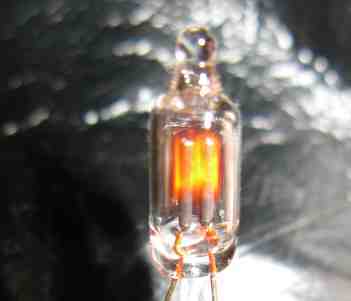
You'll notice that only the negative electrode is ionising. You can swap the wires around if you wish but the effect will be the same. The ghosting around the positive electrode is a reflection off the glass capsule.
So we can say that AC ionises both electrodes but DC ionises only one. So while it may be possible to earth a DC system without ionising one side of the circuit, with AC both active and neutral (including earth when bonded) must be ionised.
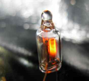
Photo by Adam Butcher
Photo by Adam Butcher